PART 3 :: ADDING A MICROCONTROLLER :: SOFTWARE
Difficulty Level: Intermediate
Since our hardware is all setup and ready for programming, we can start with the software side of things. I do advise reading through parts 1 and 2 before moving onto PART 3. You can find the links to these just before the comment section.
Introduction:
Like I’ve explained in PART 2 of this tutorial, we will be working with 3 of the most common Arduino RF libraries I found to be used with these modules. The 3 libraries are RC-Switch, Manchester and VirtualWire. I’ve also made sure that all of my example programs are well commented so I won’t be going into too much detail with the explanation of each.
Installing an External Arduino Library:
These 2 tutorials should be able to assist you if you’re finding it difficult to install new libraries for your Arduino IDE.
– Arduino – Installing additional Arduino Libraries
– Sparkfun – Installing an Arduino Library
CODING GUIDE :: RC-SWITCH
/*
  Example code for an RF-Link 433MHz Transmitter using the RC-Switch library

  Processor - ATtiny85 programmed with Arduino IDE
  Use the RC-Switch Library to send data wirelessly between 2 micro-controllers

  Find the tutorial and Receiver code here:
  "https://www.make.net.za/learn/taming-the-cheap-433mhz-rf-link-tx-rx-modules-part-3/"
*/

// Include the RC-Switch library
#include "RCSwitch.h"

// Instantiate an RC-Switch object
RCSwitch mySwitch = RCSwitch();

// Use ATtiny85 physical pin 5 to transmit (Arduino Pin 0)
#define TX_PIN      0
// LED will be connected to physical pin 3 (Arduino Pin 4)
#define LED_PIN     4

void setup() {
    // Set led pin as an output
    pinMode(LED_PIN, OUTPUT);
    // Make sure led pin is low
    digitalWrite(LED_PIN, LOW);

    // Enable transmission on defined pin
    mySwitch.enableTransmit(TX_PIN);
    // Set the desired pulse length in microseconds (Similar to baud rate)
    mySwitch.setPulseLength(500);
    // Set the amount of times to re-transmit each data packet
    mySwitch.setRepeatTransmit(4);
}

void loop() {
    // Turn on led during transmission
    digitalWrite(LED_PIN, HIGH);

    // This is the data packet that will be transmitted
    unsigned long code = 123;
    // Only the first 'length' bits of 'code' will be transmitted
    unsigned int length = 8;
    // Send the data packet
    mySwitch.send(code, length);

    // Turn off led when transmission is complete
    digitalWrite(LED_PIN, LOW);

    delay(1000);
}
To briefly explain the transmitter code :
We firstly include the RC-Switch library and instantiate an RC-Switch object to give us access to all the RC-Switch methods. We then set some properties of the object, like the pin our transmitter is connected to, the length in microseconds of each pulse and how many times we want each packet of data to be transmitted. In this example, our transmitter is connected to PB0 of the ATtiny85, the pulse length is 500us and we will re-transmit each data packet a total of of 4 times. I’ve found setting the re-transmit to 4 allows the transmitter to sync up with the receiver and safely deliver the data packet without any data corruption. This is all done in the setup loop.
In the program loop, we are turning on an LED, sending a packet of data using the RC-Switch method .send(), turning off the LED, waiting 1 second and repeating. The LED helps us see when data is being transmitted. That’s it for the transmitter code, pretty simple right?
/*
  Example code for an RF-Link 433MHz Receiver using the RC-Switch library

  Processor - Arduino Leonardo
  Use the RC-Switch Library to send data wirelessly between 2 micro-controllers

  Find the tutorial and Transmitter code here:
  "https://www.make.net.za/learn/taming-the-cheap-433mhz-rf-link-tx-rx-modules-part-3/"

*/

// include the RC-Switch library
#include "RCSwitch.h"

// instantiate an RC-Switch object
RCSwitch mySwitch = RCSwitch();

// rename the primary serial line
#define debug_Serial  Serial

// use Leonardo's Pin 3 to receive data on (Interrupt 0)
#define RX_PIN        0
// use the Leonardo's onboard LED to display data being received
#define LED_PIN       13

void setup() {
  // set led pin as an output
  pinMode(LED_PIN, OUTPUT);
  // make sure led pin is low
  digitalWrite(LED_PIN, LOW);

  // enable the serial line used for debugging
  debug_Serial.begin(9600);
  delay(100);

  // enable the RC-Switch receiver pin and start checking for RF data
  mySwitch.enableReceive(RX_PIN);
}

void loop() {
  // if data is available
  if(mySwitch.available()) {
    // turn on LED to show that data has been received
    digitalWrite(LED_PIN, HIGH);
    // display the received data on the debug serial line
    debug_Serial.print("Received value: ");
    debug_Serial.println(mySwitch.getReceivedValue());
    debug_Serial.print("Bit Length: ");
    debug_Serial.println(mySwitch.getReceivedBitlength());

    // this should be called right after receiving data
    mySwitch.resetAvailable();
    // turn the led off again
    digitalWrite(LED_PIN, LOW);
  }
}
To briefly explain the receiver code :
Like the transmitter code we include the RC-Switch library and instantiate an RC-Switch object to give us access to all the RC-Switch methods. For the receiver we also need to initialize a serial line so that we can display the received data in our serial monitor. Here I’ve set the baud rate to 9600 bits per second and I’m using the on-board LED of the Leonardo to display when RF data is being received. The only property of the RC-Switch object we need to set is the pin that is connected to the receiver module. After this we’re ready to start receiving data so we can enable the receiver interrupt using the .enableReceive() method. That completes the setup loop.
In our main loop we are basically waiting for RF data to be received by continuously checking if any valid data is available with the aptly named .available() method. The .available() method will only return true if valid data has been received. Valid data being data that has a certain combination of bits sent before each packet (known as the preamble) which tells the RC-Switch library that this is actually data it is receiving and not just RF noise. This is why we use these libraries instead of say something like USART. They screen all incoming data and only let through the stuff we want. Wonderful isn’t it! So getting back to the code, once the .available() method returns true, we turn on our LED to show that data has been received, print the received data and the bit length in our serial monitor, call the .resetAvailable() method which clears the received data from the buffers allowing us to receive new data, and finally turn off our LED.
Lastly I’d like to leave a link to the fantastic tutorial that helped me while writing this RC-Switch section of my tutorial. Keep up the great work!
– Arduino&stuff – Using Attiny with RCSwitch and RemoteSwitch
CODING GUIDE :: MANCHESTER
You can download the Manchester library ZIP file from the following link – GitHub – Manchester Arduino Library
/*
  Example code for an RF-Link 433MHz Transmitter using the Manchester Mchr3k library

  Processor - ATtiny85 programmed with Arduino IDE
  Use the Manchester Library to send data wirelessly between 2 micro-controllers

  Find the tutorial and Receiver code here:
  "https://www.make.net.za/learn/taming-the-cheap-433mhz-rf-link-tx-rx-modules-part-3/"
*/

// include the Manchester library
#include "Manchester.h"

// use attiny85 physical pin 5 to transmit (Arduino Pin 0)
#define TX_PIN      0
// led will be connected to physical pin 3 (Arduino Pin 4)
#define LED_PIN     4

// 16-bit global variable used to store data we will be transmitting
// safest to use numbers between 512 (9-bit) and 16384 (14-bit)
// numbers outside of this range do not transmit well
uint16_t transmitData = 1234;

/*
  To send an analog value from 0 - 256 do this :

  transmitData = analogValue + 1000;
*/

void setup() {
  // set led pin as an output
  pinMode(LED_PIN, OUTPUT);
  // make sure led pin is low
  digitalWrite(LED_PIN, LOW);

  // initialize transmission on the selected pin and set the baud rate to 600 bps
  // found this to be the most reliable speed for these modules
  man.setupTransmit(TX_PIN, MAN_600);
}

void loop() {
  // turn on led during transmission
  digitalWrite(LED_PIN, HIGH);

  // send the data packet
  man.transmit(transmitData);
  // 1 re-transmit for safety
  man.transmit(transmitData);

  // turn off led when transmission is complete
  digitalWrite(LED_PIN, LOW);

  delay(1000);
}
To briefly explain the transmitter code :
First we include the Manchester library which you should have installed already. Next we define the pin numbers our transmitter and LED are connected to and we initialize a global variable which contains the data we will be sending. Through a bit of trial and error, I’ve found that numbers less than 512 or greater than 16384 aren’t always sent as you would expect. I’m not sure why just yet, but when using this library I’d say it’s safer to send numbers within that range. Well that’s only if you want to receive exactly what you’re sending. You can still send lower values if you like, I’ve added a little piece of commented code to show you how. Moving on, we then initialize our transmitter pin with the man.setupTransmit() function. This function requires 2 arguments, the physical pin our transmitter is connected to and the transmission speed (baud rate) to use. I’ve found a baud rate of 600 works quite reliably, faster speeds tend to give me a small amount bit of dropout (data not being received every now and then). The list of speeds you can use are: MAN_300; MAN_600; MAN_1200; MAN_2400; MAN_4800; MAN_9600; MAN_19200; MAN_38400. That’s all for the setup loop.
In the program loop, we are turning on an LED, sending a packet of data using the man.transmit() function (with 1 manual re-transmit for safety), turning off the LED, waiting 1 second and repeating. The LED helps us see when data is being transmitted. Transmitter code done!
/*
  Example code for an RF-Link 433MHz Receiver using the Manchester Mchr3k library

  Processor - Arduino Leonardo
  Use the Manchester Library to send data wirelessly between 2 micro-controllers

  Find the tutorial and Transmitter code here:
  "https://www.make.net.za/learn/taming-the-cheap-433mhz-rf-link-tx-rx-modules-part-3/"

*/

// include the Manchester library
#include "Manchester.h"

// rename the primary serial line
#define debug_Serial  Serial

// use Leonardo's Pin 3 to receive data on
#define RX_PIN        3
// use the Leonardo's onboard LED to display data being received
#define LED_PIN       13

// 16-bit global variable to store received data
uint16_t receivedData = 0;

/*
  To receive an analog value from 0 - 256 do this after receiving :

  uint16_t finalValue = receivedData - 1000;
*/

void setup() {
  // set led pin as an output
  pinMode(LED_PIN, OUTPUT);
  // make sure led pin is low
  digitalWrite(LED_PIN, LOW);

  // enable the serial line used for debugging
  debug_Serial.begin(9600);
  delay(100);

  // initialize reception on the selected pin and set the baud rate to 600 bps
  // ie. Make sure this baud rate is the same as your transmitter
  man.setupReceive(RX_PIN, MAN_600);
  // enable the receiver pin and start checking for RF data
  man.beginReceive();
}

void loop() {
  // if data is available
  if(man.receiveComplete()) {
    // save the received data
    receivedData = man.getMessage();
    //start listening for the next message right after you retrieve a message
    man.beginReceive();

    // turn on LED to show that data has been received
    digitalWrite(LED_PIN, HIGH);

    // display the received data on the debug serial line
    debug_Serial.print("Received value: ");
    debug_Serial.println(receivedData);

    // turn the led off again
    digitalWrite(LED_PIN, LOW);
  }
}
To briefly explain the receiver code :
Like the transmitter code, we firstly include the Manchester library, define the pin numbers our receiver and LED are connected to, and initialize a global variable which will hold the received data once it has been received. We also need to initialize a serial line so that we can display the received data in our serial monitor. I’ve set the baud rate to 9600 bits per second and I’m using the on-board LED of the Leonardo to display when RF data is being received. I’ve added a little piece of commented example code to show you how to receive a value lower than 512 from the transmitter, if you were wondering. Now the only 2 arguments we need to pass to the Manchester function is the pin that is connected to the receiver module and the baud rate. After this has been done we’re ready to start receiving data so we can enable the receiver using the man.beginReceive() function. This completes the setup loop.
In our main loop we are basically waiting for RF data to be received by continuously checking if any valid data is available with the man.receiveComplete() function. This function will only return true if valid data has been received. Valid data being data that has a certain combination of bits sent before each packet (known as the preamble) which tells the Manchester library that this is actually data it is receiving and not just RF noise. Once man.receiveComplete() returns true, we save the received data in our global variable, call the man.beginReceive() function again to allow us to receive new data, turn on our LED to show that data has been received, print the received data in our serial monitor, and finally turn our LED off again.
Note if you’ve used a Leonardo for the receiver like I have :
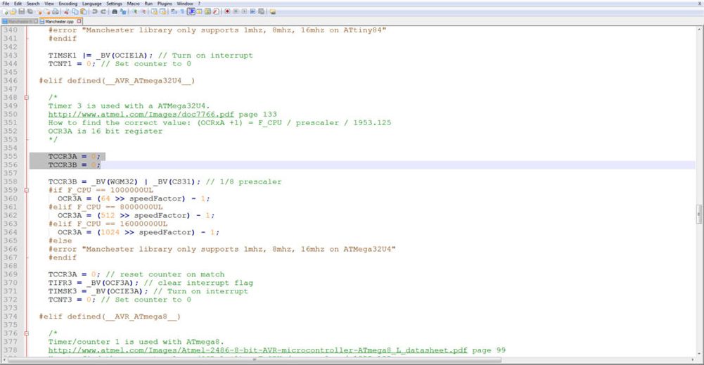
If you’ve set up everything correctly and you just can’t figure why this darn thing won’t receive any data, let me save you the trouble. Even though this library is supposed to work with an ATMEGA32u4 (microcontroller used in a Leonardo), it really doesn’t. Not until you make a small modification.
It really is quite a straight forward thing to do. First you need to locate the “Manchester.cpp” file, it should be in the “Documents\Arduino\libraries\arduino-libs-manchester-master\” folder. This is the directory where all of my Arduino libraries are installed to. Once you’ve found it, you need to add 2 lines of code to the file and that’s it, you’re done. Have a look at this screenshot which shows you exactly where and what to add.
I found this magical fix here :
– Arduino Forum
– GitHub Solution
Proof That It Works:
I’m not going to post a video of this code working because it will be very similar to the video for the RC-Switch section. You’ll just have to take my word that I’ve tested everything and it’s all working as it should be. Weeeell as long you’ve followed my tutorial correctly that is.
Lastly I’d like to leave some links to the fantastic tutorials that helped me while writing this Manchester section of my tutorial. Keep up the great work!
– Mchr3k – Arduino Manchester Encoding
– ArduinoDIY – Sending wireless data from one Attiny85 to another
CODING GUIDE :: VIRTUAL WIRE
Coming soon …