Features / Specs
- Relay Contact Configuration: Single Pole Double Throw
- Relay Contact Rating: 10A @ 250VAC; 10A @ 125VAC; 10A @ 30VDC; 10A @ 28VDC
- Relay Coil Voltage: 5VDC
- Optocoupler Part Number: Sharp PC817C
- Flyback protection diode placed across each relay coil to suppress back EMF
- LEDs to indicate that relays have been triggered / LED On = Relay Coil Energized
- Control inputs “IN1” to “IN4” must be pulled low (0VDC) to energize each relay coil respectively
- Supply selection jumper allows the user to provide a separate supply voltage to power the relay coils if needed.Shorting “JD-VCC” and “VCC” will power the relay coils from the “VCC” pin
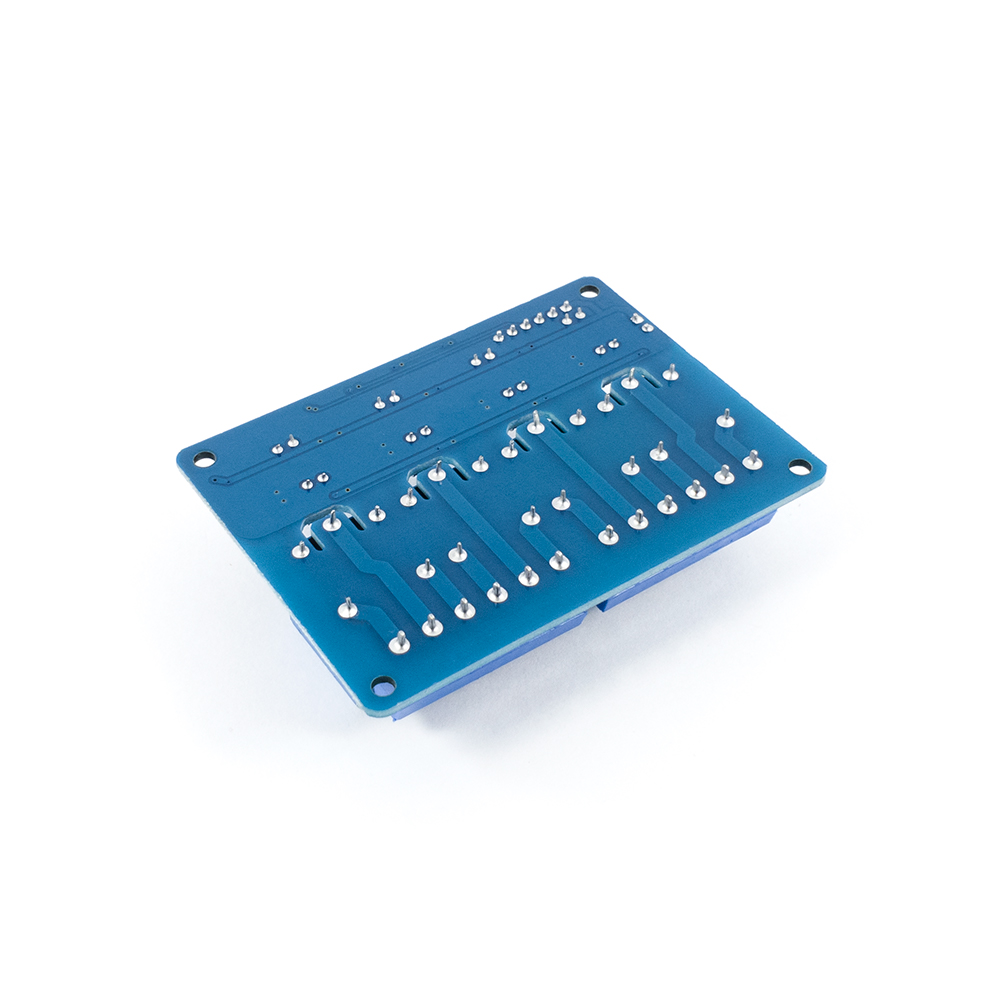
- Dimensions: ~(75.5mm x 55.3mm x 19mm)
- Mounting Hole Diameter: ~3mm
- Mounting Hole Spacing (Centre to Centre): ~68mm / ~47.9mm
Basic Operation Overview
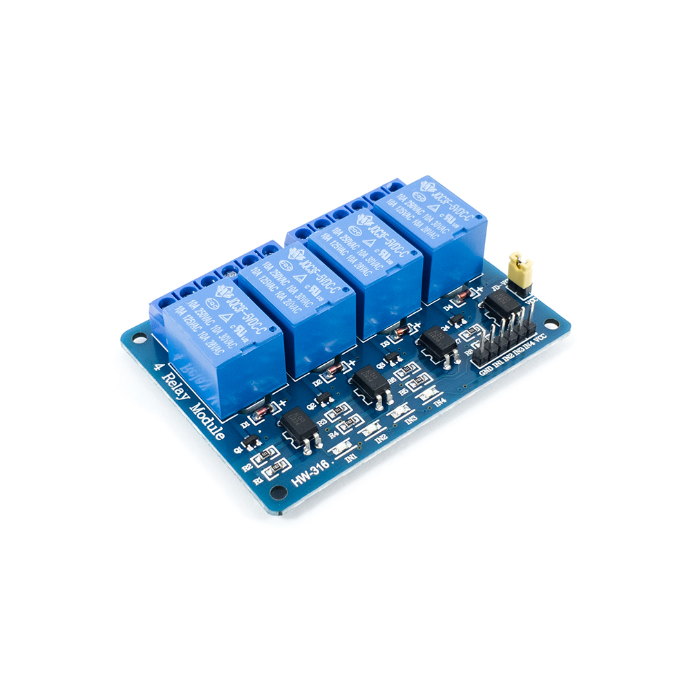
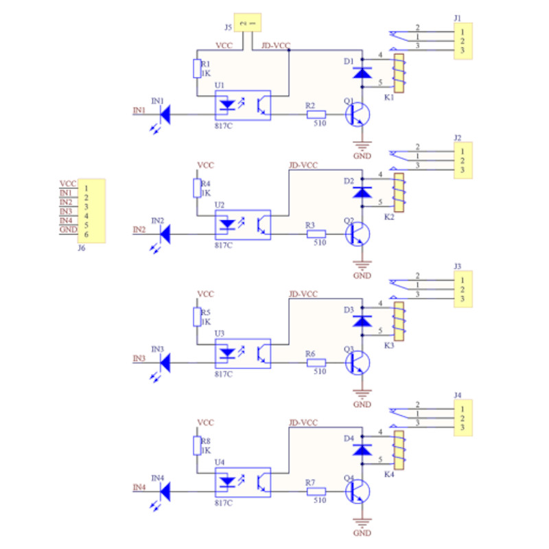
Starting at the input side of the optocouplers, the 6-Way pin header is what you will use to control each of the relays and connect your control voltage supply. There are “GND” and VCC” pins for your control voltage, and “IN1” to “IN4” pins for your digital control signals. Each digital input pin is connected to an indication LED which is connected in series to the optocoupler LED and a 1k-Ohm resistor. Measured volt drop on the indication LED is ~1.8V and on the opto LED it is ~1.1V. Measurement was taken with a control supply voltage of 5VDC. A low level signal turns on both the opto and indication LEDs, while a high level signal (Same level as “VCC”) will turn both off.
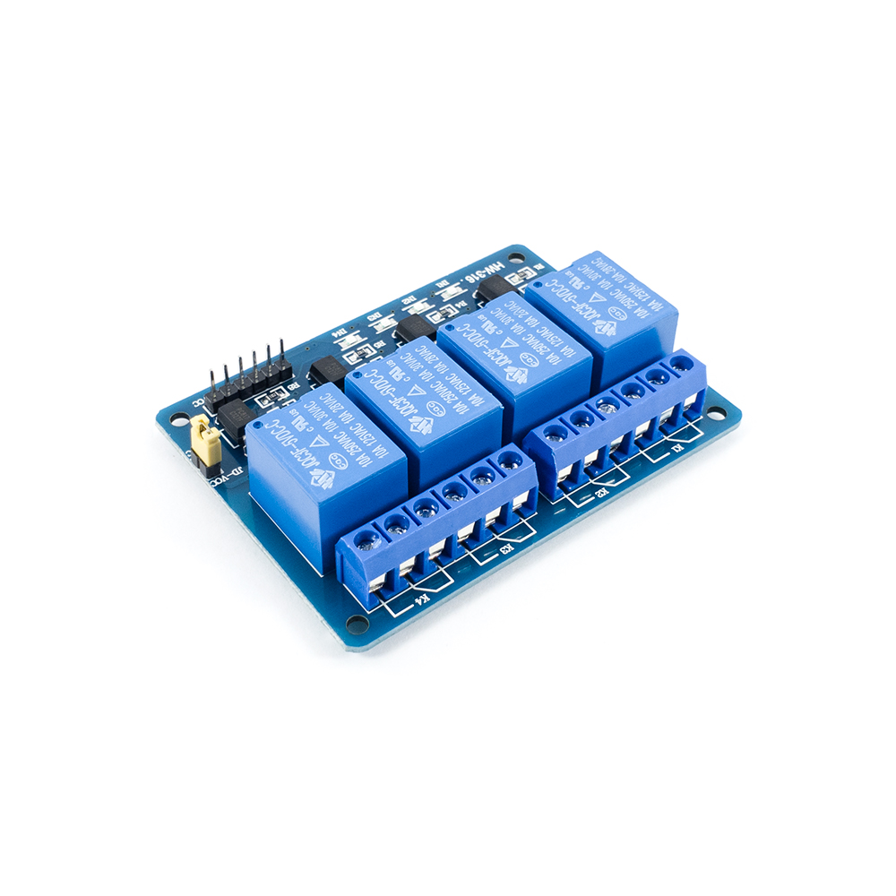
Moving on to the output side of the optocouplers. The output NPN transistor of the optocoupler drives a second NPN transistor which in turn, drives the relay coil. Refer to the schematic for detailed connections. Measured resistance of the relay coil is ~70 Ohms. Each relay coil has diode connected in reverse polarity across it to suppress any back EMF generated by the coil. The PCB’s also have milled out air gaps between the contact pins and nearby control circuitry tracks / pins. This helps prevent high voltage on the contacts from flashing over to the control circuitry.
One last thing worth mentioning is the single settings jumper with the labels “JD-VCC” and “VCC”. If these 2 pins are shorted, you will be able to supply both the input and output optocoupler circuitry from the “VCC” pin on the 6-Way pin header. If the 2 pins are disconnected, then you can provide separate supply voltages for the optocoupler input and output circuitry. These supply voltages will be optically isolated and any damage to the output supply should not have any effect on the input supply.